Here you will find answers to OSPF Questions
Question 1
Which information is carried in an OSPFv3 intra-area-prefix LSA?
A. IPv6 prefixes
B. link-local addresses
C. solicited node multicast addresses
D. IPv6 prefixes and topology information
B. link-local addresses
C. solicited node multicast addresses
D. IPv6 prefixes and topology information
Answer: A
Explanation
The OSPFv3’s new LSA, the Intra-area Prefix LSA (type 9), handles intra-area network information that was previously included in OSPFv2 type 2 LSAs. It is used in order to advertise one or more IPv6 prefixes. The prefixes are associated with router segment, stub network segment or transit network segment.
Intra-area prefix LSAs (type 9) & Inter-Area-Prefix-LSA (type 3) carry all IPv6 prefix information, which, in IPv4, is included in router LSAs and network LSAs.
Note: An address prefix is represented by three fields: prefix length, prefix options, and address prefix. In OSPFv3, addresses for these LSAs are expressed as prefix, prefix length instead of address, mask.
Question 2
Which one of these statements is true of OSPF type 5 LSAs?
A. They are used to summarize area routes to other areas.
B. They are used in not-so-stubby areas to propagate external routes.
C. They are used to notify areas of the ASBR.
D. They are flooded to all areas (external route).
B. They are used in not-so-stubby areas to propagate external routes.
C. They are used to notify areas of the ASBR.
D. They are flooded to all areas (external route).
Answer: D
Explanation
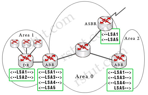
Type 5 external link LSAs are used to advertise external routes originated from an ASBR. They are flooded through the whole OSPF domain.

(Note: The dashed arrows show the directions of LSAs in this example)
Below is a summary of OSPF Link-state advertisements (LSAs)
Router link LSA (Type 1) – Each router generates a Type 1 LSA that lists its neighbors and the cost to each. LSA Type 1 is only flooded inside the router’s area, does not cross ABR.
Network link LSA (Type 2) – is sent out by the designated router (DR) and lists all the routers on the segment it is adjacent to. Types 2 are flooded within its area only; does not cross ABR. Type 1 & type 2 are the basis of SPF path selection.
Summary link LSA (Type 3) – ABRs generate this LSA to send between areas (so type 3 is called inter-area link). It lists the networks inside other areas but still belonging to the autonomous system and aggregates routes. Summary links are injected by the ABR from the backbone into other areas and from other areas into the backbone.
Summary LSA (Type 4) – Generated by the ABR to describe routes to ASBRs. In the above example, the only ASBR belongs to area 0 so the two ABRs send LSA Type 4 to area 1 & area 2 (not vice versa). This is an indication of the existence of the ASBR in area 0. Note: Type 4 LSAs contain the router ID of the ASBR.
External Link LSA (LSA 5) – Generated by ASBR to describe routes redistributed into the area (which means networks from other autonomous systems). These routes appear as E1 or E2 in the routing table. E2 (default) uses a static cost throughout the OSPF domain as it only takes the cost into account that is reported at redistribution. E1 uses a cumulative cost of the cost reported into the OSPF domain at redistribution plus the local cost to the ASBR. Type 5 LSAs flood throughout the entire autonomous system but notice that Stubby Area and Totally Stubby Area do not accept Type 5.
Multicast LSA (Type 6) are specialized LSAs that are used in multicast OSPF applications.
NSSA External LSA (Type 7) – Generated by an ASBR inside a NSSA to describe routes redistributed into the NSSA. LSA 7 is translated into LSA 5 as it leaves the NSSA. These routes appear as N1 or N2 in the ip routing table inside the NSSA. Much like LSA 5, N2 is a static cost while N1 is a cumulative cost that includes the cost upto the ASBR
(Reference: http://www.cisco.com/en/US/tech/tk365/technologies_white_paper09186a0080094e9e.shtml#appa1)
Question 3
Which OSPF LSA type does an ASBR use to originate a default route into an area?
A. LSA 1
B. LSA 3
C. LSA 4
D. LSA 5
E. LSA 7
B. LSA 3
C. LSA 4
D. LSA 5
E. LSA 7
Answer: D
Explanation
By default, the OSPF router does not generate a default route into the OSPF domain. In order for OSPF to generate a default route, you must use thedefault-information originate command. With this command, the router will advertise type 5 LSA with a link ID of 0.0.0.0.
(Reference: http://www.cisco.com/en/US/tech/tk365/technologies_configuration_example09186a00801ec9f0.shtml)
Question 4
Refer to the exhibit. Routers A and B are directly connected and running OSPF, but they are unable to form a neighbor relationship. What is the most likely cause?
Router A relevant configuration:
interface fa0/0 ip address 10.10.1.1 255.255.252.0 ip ospf cost 512
router ospf 1
network 10.10.1.0 0.0.0.255 area 0
Router B relevant configuration:
interface fa0/0 ip address 10.10.2.2 255.255.252.0 ip mtu 512
router ospf 10
network 10.10.2.0 0.0.0.255 area 0 |
A. The routers are not on the same network.
B. The network statements do not match.
C. The process number does not match.
D. The MTU does not match.
E. The OSPF cost does not match.
F. There is a physical issue with the cable.
B. The network statements do not match.
C. The process number does not match.
D. The MTU does not match.
E. The OSPF cost does not match.
F. There is a physical issue with the cable.
Answer: D
Explanation
OSPF sends the interface MTU in a database description packet. If there is a MTU mis-match, OSPF will not form an adjacency and they are stuck in exstart/exchange state. The interface MTU option was added in RFC 2178. Previously, there was no mechanism to detect the interface MTU mismatch. This option was added in Cisco IOS Software Release 12.0.3 and later.
If the router with the higher MTU sends a packet larger that the MTU set on the neighboring router, the neighboring router ignores the packet and the neighbor state remains in exstart.
Note: By default, the MTU for Ethernet is 1500 bytes. We can check the OSPF adjacency process with the command “show ip ospf neighbor”.
Question 5
Which two of these steps are minimum requirements to configure OSPFv3 under IPv6? (Choose two)
A. Configure a routing process using the command ipv6 router ospf [process-id].
B. Add the network statement for the interfaces on which OSPF will run.
C. Configure OSPF on the interface that it will run on.
D. Use the passive-interface command on the interfaces on which OSPF should not run.
E. Enable routing.
B. Add the network statement for the interfaces on which OSPF will run.
C. Configure OSPF on the interface that it will run on.
D. Use the passive-interface command on the interfaces on which OSPF should not run.
E. Enable routing.
Answer: C E
Explanation
The first step to configure OSPFv3 under IPv6 is to enable IPv6 unicast routing:
R1(config)# ipv6 unicast-routing
Also we need to enable the OSPF process:
R1(config)# ipv6 router ospf 1
There are a few changes in configuring OSPFv3 vs OSPF for IPv4. Instead of using the “network” and “area” commands in ospf router configuration mode you now configure OSPFv3 on a per interface basis using the ipv6 ospf
area
R1(config)# interface fa0/0
R1(config-if)# ipv6 ospf 1 area 0
R1(config-if)# ipv6 ospf 1 area 0
Note: The “network” command does not exist in OSPFv3.
Question 6
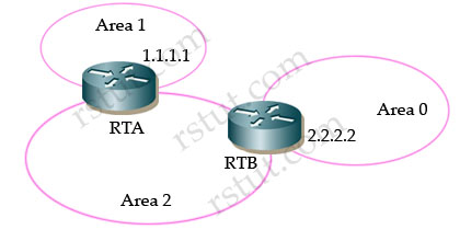
Refer to the exhibit. How would you get the 1.1.1.1 network into the OSPF database?

A. Configure RTA as an ASBR.
B. Redistribute connected routes on RTA into OSPF.
C. Set up a virtual link between area 1 and area 0.
D. Set up a virtual link between area 1 and area 2.
E. Add a static route into RTB and enter it into OSPF.
F. Place a network 1.1.1.0 0.0.0.0 command into RTB.
G. Set up a unique router ID on RTA using an RFC 1918 address.
H. Change area 0 on RTB to area 1
Answer: C
Explanation
Recall that in OSPF, area 0 is called backbone area and all other areas connect directly to it. In the exhibit above, area 1 is not directly connected with area 0 so we need to set up a virtual link between area 1 & area 0 so that the networks in area 1 can be recognized in area 0. The virtual-link configuration is shown below:
RTB(config)#router ospf 1
RTB(config-router)#area 2 virtual-link 1.1.1.1
RTB(config-router)#area 2 virtual-link 1.1.1.1
RTA(config)#router ospf 1
RTA(config-router)#area 2 virtual-link 2.2.2.2
RTA(config-router)#area 2 virtual-link 2.2.2.2
Notice that the router-id in the “area … virtual-link ” command is the router-id of the neighboring router.
Question 7
The core of a network has four routers connected in a square design with Gigabit Ethernet links using /30 subnets. The network is used to carry voice traffic and other applications. Convergence time is taking more than expected. Which three actions would you take to improve OSPF convergence time? (Choose three)
A. Increase MTU of the interfaces to accommodate larger OSPF packets.
B. Change the network type to point-to-point on those links.
C. Reduce SPF initial timer.
D. Increase hello interval to avoid adjacency flapping.
E. Enable OSPF.
B. Change the network type to point-to-point on those links.
C. Reduce SPF initial timer.
D. Increase hello interval to avoid adjacency flapping.
E. Enable OSPF.
Answer: B C E
Sign up here with your email

ConversionConversion EmoticonEmoticon