
Knowing how to convert a physical topology into a logical topology that suits your demand is the first thing you have to do for your network to get up and run. In practical most of the networks are connected like this:
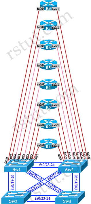
As you can see, all the routers are connected to two switches Sw1 & Sw2. If the network is large enough, Sw1 & Sw2 should belong to Core layer which requires high speed switching because they have to do hardest work in the network. They should be powerful to mitigate congestion if occurs. Redundancy is also very important in this layer by providing multiple paths so that when a link goes down packets can still travel to the destination. Sw3 & Sw4 requires less power to proceed traffic and they should belong to Distribution layer. The last layer, which is not presented here is the Access Layer where switches are connected directly to the end users/terminals. In fact Sw3 and Sw4 can be used in Access Layer if the network is not large.
So how can we convert a physical topology to a logical topology as shown below?

The answer is we will need to use VLAN, trunking, subinterfaces to achieve this. Let’s start with the first section of R1-R2-R6.
Note: You can download the Initial Config & Final Config of this lab here (open with Packet Tracer v5.3.3 or above):http://www.rstut.com/download/Physical_Topology_to_Logical_Topology.zip. We tested and all the configuration in this lab worked very well.
Section R1-R2-R6
We see all three routers R1, R2 & R6 use fa0/0 interfaces to connect to each other in this section and they all are connected to Sw1 in the physical topology so we only need to assign VLAN 126 to three corresponding ports on Sw1.

| SW1: interface range fa0/1 – 2, fa0/6 switchport access vlan 126 |
After typing above commands we will see a message like this:
| % Access VLAN does not exist. Creating vlan 126 |
That means SW1 does not have Vlan 126 previously so it created one automatically.
Of course we will assign IP addresses on these routers and “no shut” them so that we can ping among them:
| R1: interface fa0/0 ip address 10.10.126.1 255.255.255.0 no shutdown | R2: interface fa0/0 ip address 10.10.126.2 255.255.255.0 no shutdown | R6: interface fa0/0 ip address 10.10.126.6 255.255.255.0 no shutdown |
Now we can ping between them successfully:
| R1#ping 10.10.126.2
Type escape sequence to abort.
Sending 5, 100-byte ICMP Echos to 10.10.126.2, timeout is 2 seconds:
.!!!!
Success rate is 80 percent (4/5), round-trip min/avg/max = 0/0/1 ms
|
The first ping fails because whenever a router first sends a packet to a next-hop that has no entry in the ARP table, it has to send out an ARP Request first and wait for a reply. That waiting time causes the first packet to be dropped.
Section R2-R3
From the physical topology we learn that fa0/1 of R2 is connecting to Sw2 while fa0/0 of R3 is connecting to Sw1. Therefore if we want to connect these two interfaces we have to configure a trunking link between Sw1 & Sw2. In this part we only set fa0/23 of Sw1 & Sw2 as trunk links while turning off other switch-to-switch ports to make the explanation simple.
Sw1 & Sw2:
interface fa0/23
switchport trunk encapsulation dot1q switchport mode trunk no shutdown |
Fa0/1 of R2 is connecting to SW2 so we configure Vlan 23 on this switch:
| Sw2: interface fa0/2 switchport access vlan 23 no shutdown |
Configure IP address on fa0/1 of R2:
| R2: interface fa0/1 ip address 10.10.23.2 255.255.255.0 no shutdown |
We see on R3, interface fa0/0 is connected to 2 different networks (one is R2-R3, the other is R3-R4-R5) so we have to use sub-interface on R3.
| R3: interface fa0/0 no shut interface fa0/0.23 encapsulation dot1q 23 ip address 10.10.23.3 255.255.255.0 |
on Sw1 we have to declare the port connected to R3 as trunk as we are using subinterface on R3.
| Sw1: interface fa0/3 switchport trunk encapsulation dot1q switchport mode trunk |
Notice that SW1 still does not have Vlan 23 because we set trunking on fa0/3 so we have to manually createVlan 23 on SW1:
| Sw1(config)#vlan 23 |
Note: If we don’t create Vlan 23 on Sw1, it will drop frames belong to Vlan 23 sent to it.
In the next part we will continue learning how to configure Section R3-R4-R5 & Section R6-R7-R8
We re-post the logical topology here so that you don’t have go back and forth viewing it:
Section R3-R4-R5
R3-R4 connection is same as R1-R2-R3 while R3-R5 & R4-R5 connections are same as R2-R3 so we only post the configuration here:
| R3: interface fa0/0.345 encapsulation dot1q 345 ip address 10.10.34.3 255.255.255.0 | R4: interface fa0/0 ip address 10.10.34.4 255.255.255.0 no shutdown | R5: interface fa0/1 ip address 10.10.34.5 255.255.255.0 no shutdown |
| Sw1: interface fa0/4 switchport access vlan 345 | Sw2: interface fa0/5 switchport access vlan 345 |
Section R6-R7-R8
| R6: interface fa0/1 ip address 10.10.67.6 255.255.255.0 no shutdown | R7: interface fa0/1 ip address 10.10.67.7 255.255.255.0 no shutdown | R8: interface fa0/0 ip address 10.10.67.8 255.255.255.0 no shutdown |
| SW1: interface fa0/8 switchport access vlan 678 | SW2: interface range fa0/6 – 7 switchport access vlan 678 |
Note: If the ports on the two switches are turned off you need to turn them on.
Sign up here with your email
ConversionConversion EmoticonEmoticon